
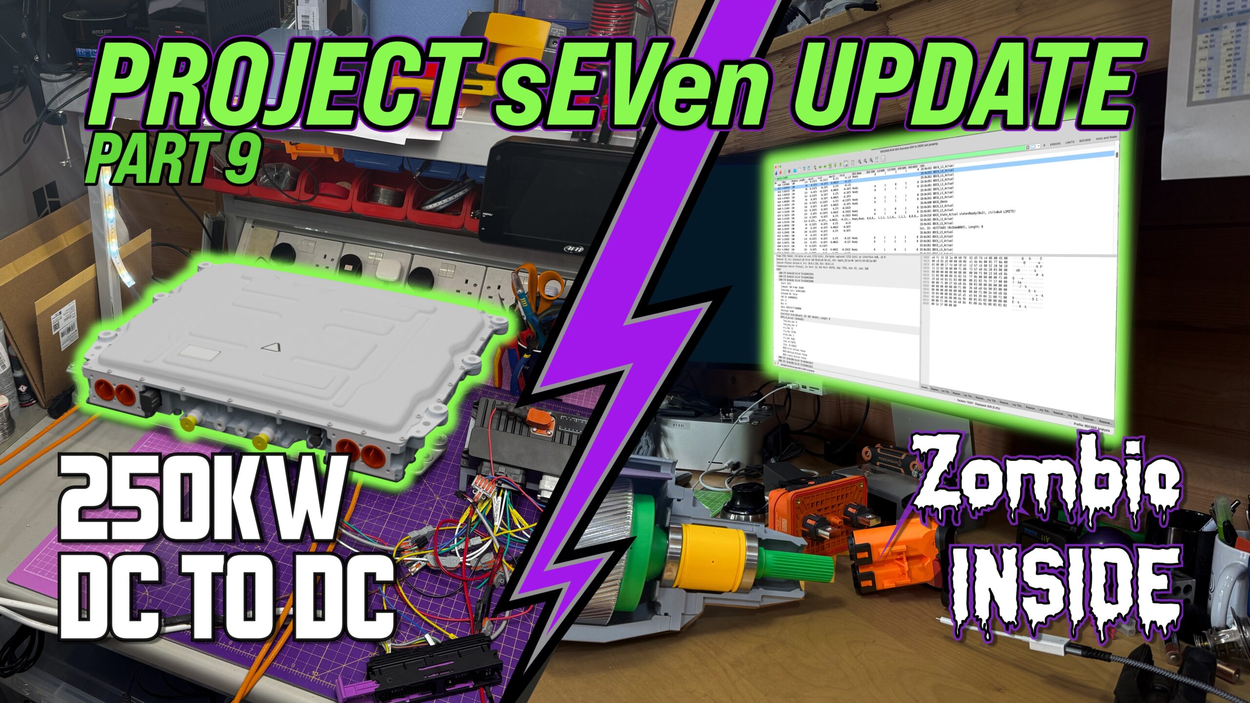
Another video out…
Project Update
Well I didn’t kill myself, that’s always a bonus!
In fact I didn’t get anywhere near… yet!
This post is a bit late, I wrote it a few weeks ago but didn’t finish it off… but here it is now 🙂
This is where things start to get real. Until now I’ve been playing around with mechanicals, a bit of 3D scanning and some low voltage electronics. But now I need to get the Traction DC2DC converter running.
Background
So, I’ve
- bought a project car,
- got it road legal,
- pulled it apart and scanned it
- Then we got into a rabbit hole with gearboxes
But the whole gist of the project revolves around the motor. Switching a 2.0L Duratec for an electric motor in a Caterham Seven is no mean feat. There’s just so little room. I wanted to try and achieve the same performance in the conversion as I had in my 420R, which meant I was going to need about 200+bhp and a sensible range to be able to do some sensible road trips that didn’t just turn into a “Public EV charging stations of the UK” tour.
But there’s the problem. I couldn’t find a motor that had enough power and that would fit in the car. I’ve covered this a few times, so won’t go over it again, but I do still get people ask me why I ended up where I am.
And the motor choice ended up creating three core design decisions:
- Motor
- DC to DC Converter
- Gearbox
The Motor
So, the reason comes back to the motor. The only motor I could find that would deliver the power I wanted AND would fit in the car (a bit of basic requirement) was the Helix SPX-177 – which critically sits in the transmission tunnel of my SV chassis.
But that motor, and it’s associated inverter, is an 800V system.
And that meant I’d either need to find a battery pack design that could deliver at least somewhere near the 800V, or I’d have to think of another way of getting 800V DC to the inverter.
No matter how I tried to slice it, I couldn’t find an 800V battery pack solution. The problem always came down to volumetric density. I didn’t care too much about gravimetric, that would just have to be what it was, but the amount of kWh I could fit in any given volume was going to be my problem. And I couldn’t make anything work.
So about the time I was thinking about this, back in 2024, I came across a solution – probably not an elegant solution, in fact a bit of a sledgehammer to crack this nut, but it was at least a solution. And that was to use a ma-hoosive DC2DC converter. Something that would convert from whatever maximum voltage I could cram into the car, to the 800V I needed.
DC to DC Converter
Bring in the Brusa BDC668. Brusa seems to have developed this for the Hydrogen fuel cell market – where the fuel cell voltage are usually quite low and need to be boosted up to the drivetrain voltage. Perfect for what I wanted, if not a little of the big side – only just fitting in my chassis.
So this component, the DC to DC Converter, takes whatever voltage I can cram into the car and converts it to the 800V I need for the motor.
Gearbox
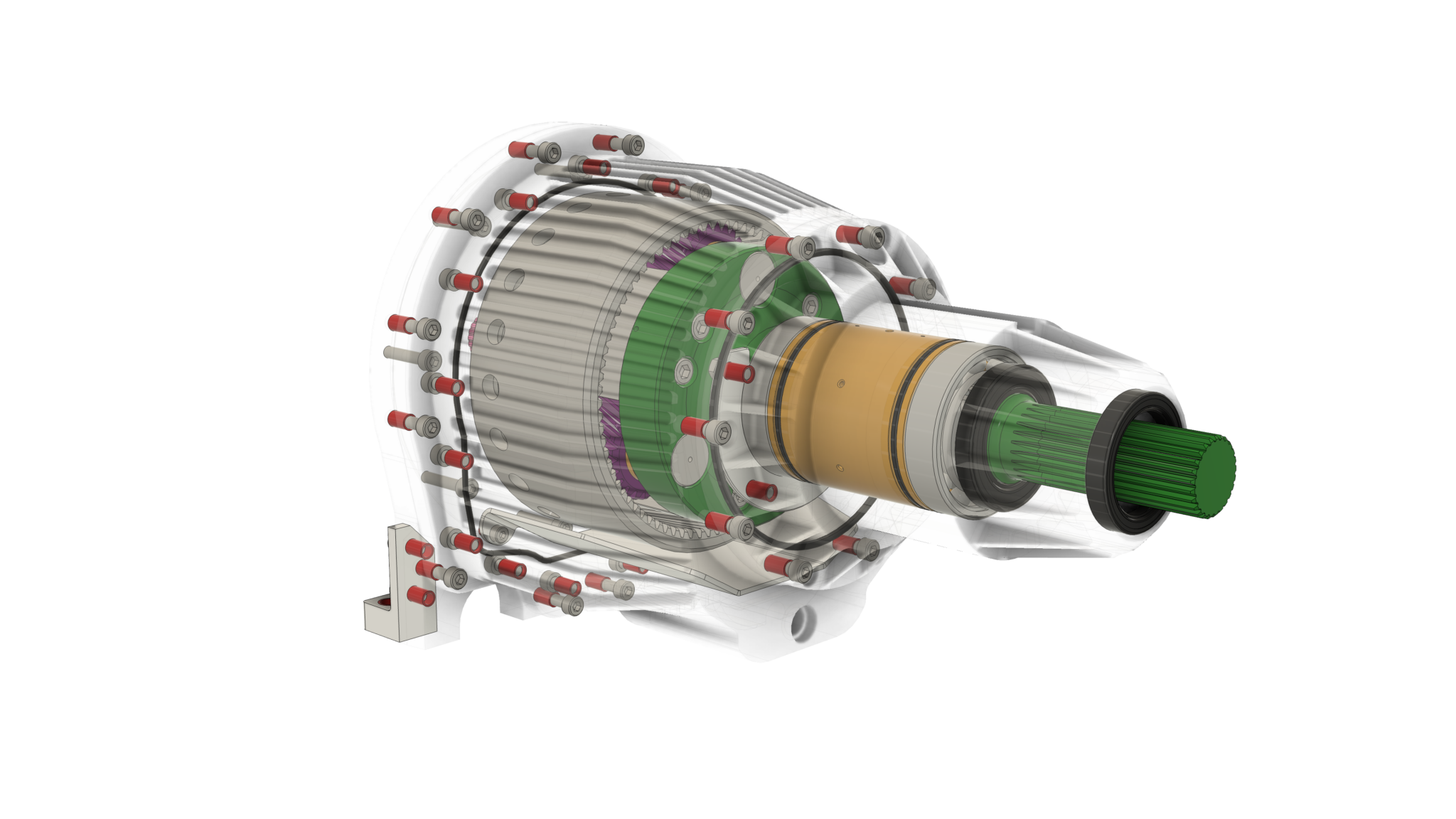
The next problem the motor threw up was that to achieve its max power it needed to run at up to 24,000rpm (there’s some caveats there that I won’t get into here).
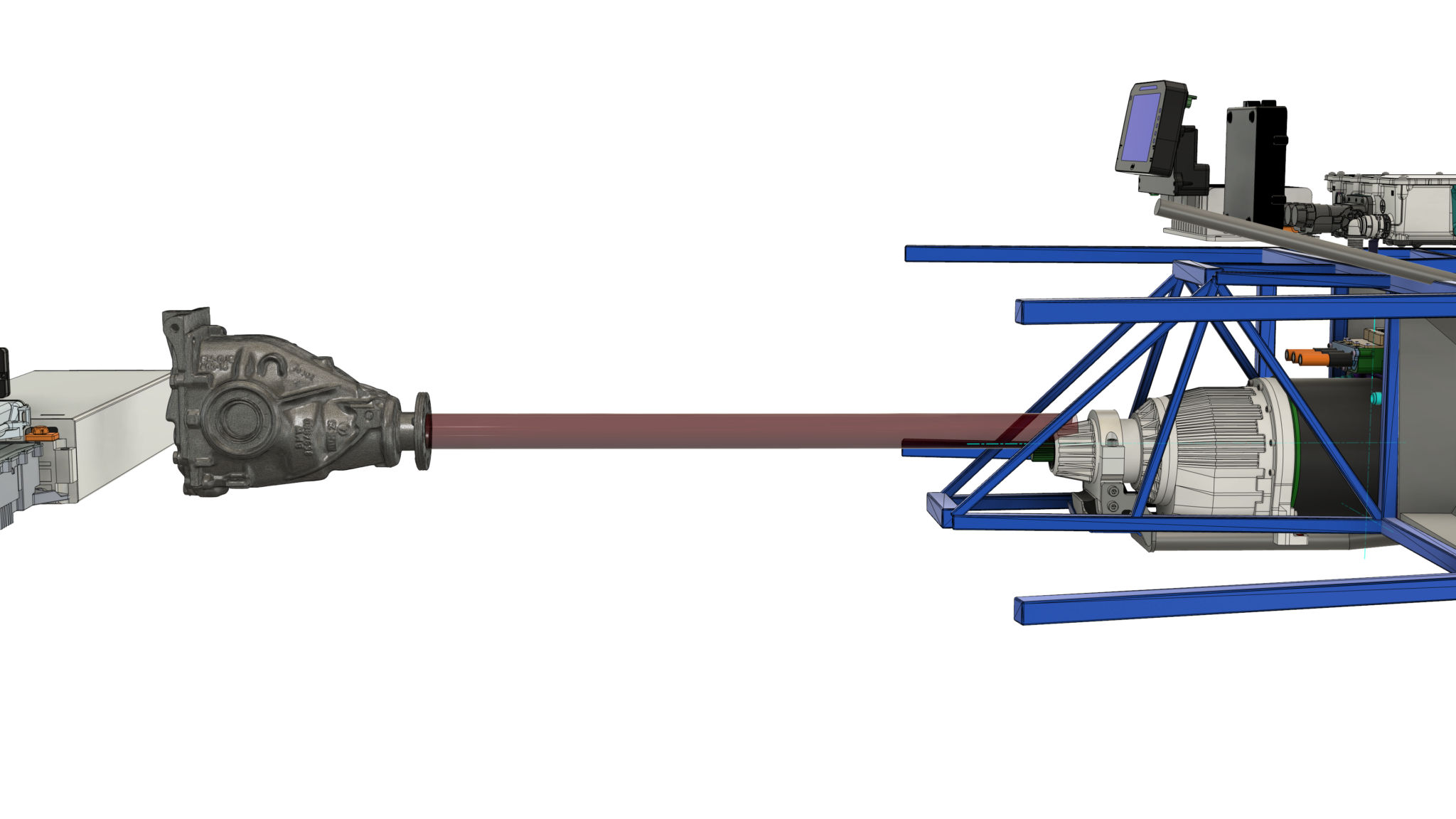
A Caterham Seven needs about 2,000 rpm at the wheel to deliver 120+mph. And because the motor was fitting in the front of the transmission tunnel, I could also retain the prop-shaft and crucially the diff.
With the combination of 24,000rpm motor, 2,000rpm at the wheel and a 3.6ratio differential, I was light on gearing. 2,000rpm multiplied by the 3.6 diff ratio gets you to about the max speed of the Duratec motor (of course) or about 7,5000rpm. But my motor’s spinning at 24,000, I’m way short of being able to use the full speed of the motor.
So I need another gearbox between the electric motor and the differential… of about 3.5:1.
It also helped that a gearbox on the motor would bridge the physical gap to the prop-shaft. A gap that couldn’t really be stretched by just making the prop-shaft longer… increasing the prop-shaft length reduces it’s maximum speed, and extending one all the way from the diff to where I could realistically shove a motor down the transmission tunnel resulted in a max speed way below the 7000 rpm I needed. So a gearbox helps to bridge the maximum prop-shaft length.
So… long story short:
- I needed the motor I chose because it was the only one that fit
- Which meant I needed an massive DC2DC converter
- And also a new gearbox
Those are the main biggies, when it comes to project choices. I’m sure others may have come to a different set of conclusions from the ones I made… but of the 4 other Seven conversions that I’ve got close to, 3 have made some sort of compromise similar to mine.
Bringing Up the DC2DC Converter
So given all of that, I needed to get all my new components up and running.
I had initially thought I’d get the battery pack running first, along with the charging and battery management for it.
But I soon realised, with a set of ID3 batteries that I’d just bought and that were fully charged, I actually couldn’t charge them until I’d taken some energy out of them. And I might as well get the drivetrain running first, to do exactly that.
And the first chunk of the drivetrain I’d need to get going was to be able to generate the 800V needed by the inverter and motor from somewhere, so why not get the traction DC2DC converter running first (there’s another low-voltage DC2DC that manages the 12V battery recharging, so I need to refer the the Brusa unit a the traction-DC2DC).
Now, this Brusa traction-DC2DC converter isn’t just something you plug in, turn on and it does its thang. It needs to be programmed. And that gets done on a CANbus.
So I need a reasonably intelligent device sat on the Brusa’s CANbus telling it what to do.
I originally thought an AIM Technologies PDM could do that.
It would also be able to soft-fuse and manage the rest of the 12V systems in the car, but in the end I decided it wasn’t programmable enough.
Which is what led me to the EVBMW.com, OpenInverter.org ZombieVerter. This project was originally conceived to control Tesla drive units. But since I first looked at it a few years ago it has matured to support other drivetrains and also more flexibility in its software model. So I selected the ZombieVerter as my vehicle control unit – the brain of the car.
(Just to be clear, the ZombieVerter is actually quite a small brain, with a single core STM32 processor. The DC2DC converter and Inverter almost certainly have more processing power than the ZombieVerter “vehicle brain”, but you’ll just have to run with the analogy for the moment).
And that gets us to the first big project task.
To get the Traction-DC2DC running, I’ll also need:
- to get the ZombieVerter running so it can program the T-DC2DC over CANbus AND
- I’ll need to get the AIM PDM running so I can control the various 12V devices (T-DC2DC, Zombie, etc).
AIM PDM
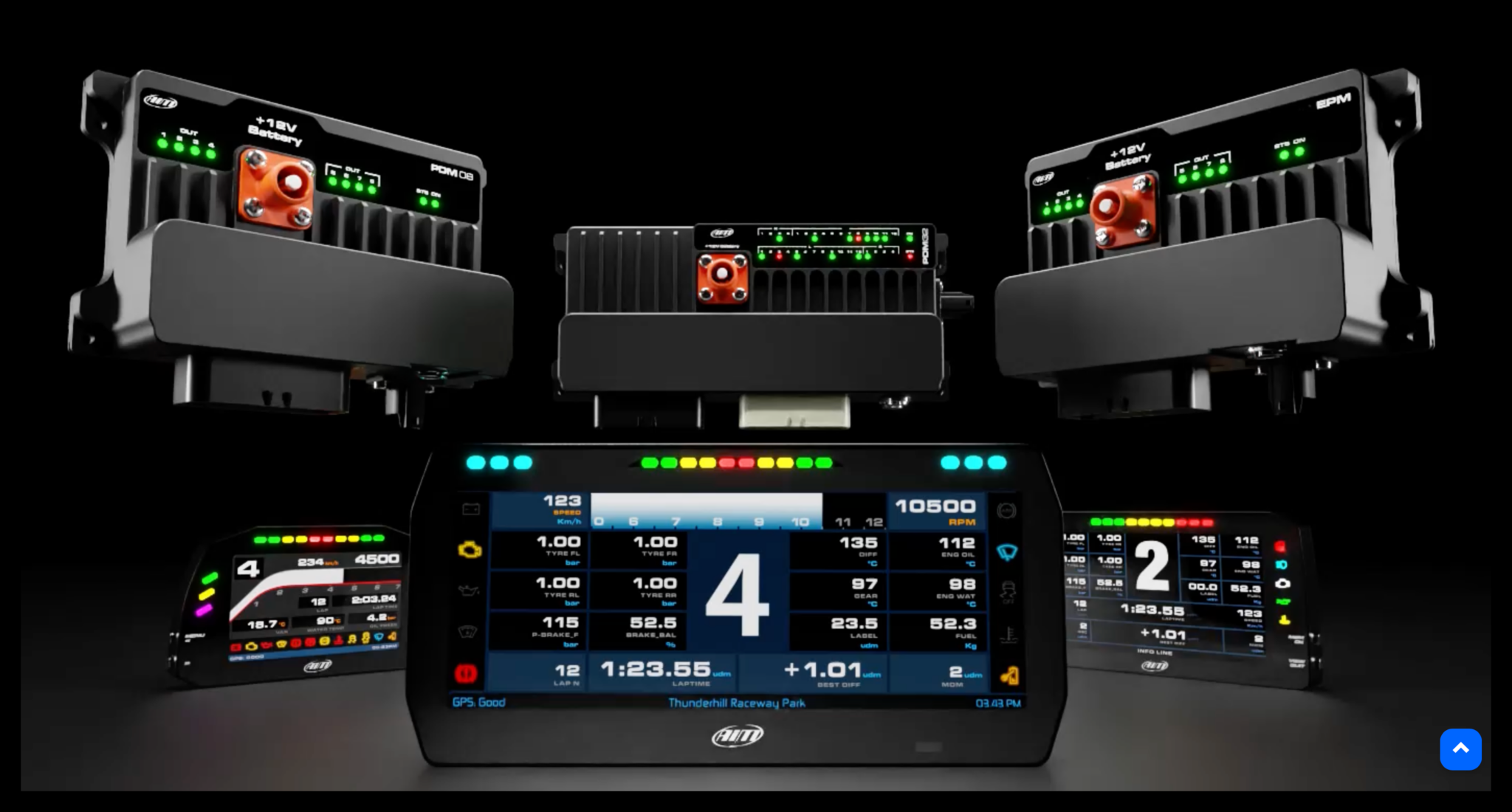
The AIM PDM is a bit of a luxury. In theory I could just use regular thermal fuses and be done with it. But a project like this has different power needs at different stages of the project. Early on, I want to be treading carefully… keeping current limits low until I get confidence in the electronics, electrical and software.
So a PDM makes a lot of senses. I can run different configurations from the AIM Race Studio software – setting various limits for all the different components depending on what I’m testing. I can have a low-current config when I add a new device and move to higher levels configs as I get more confidence. That’s a whole lot better than using regular blow-able fuses.
Getting the AIM PDM to work was a bit of a brain-ache. It all makes perfect sense when you know how it works, but it’s not at all intuitive… IMHO.
My initial bring-up was hampered by a bad USB cable (spent a few days trying to figure that out) and then getting the 12 button keypad to work was also a few days scratching my head until the AIM support guy did a screen share with me and could say the keypad had a bad config. Both issues were resolved really quilky by AIM, but even so… frustrating.
But the idea is that the AIM PDM will do the basic 12V powering of the new EV bits. I’ll leave the existing 12V fuse board in the Caterham for the moment, no need to break something that’s working fine at the moment. Eventually the whole car 12v will be switched the the AIM, but not now.
I also have a 6-inch display connected to the PDM. That may get used as a main dash-screen (removing the dials in the current dash) or I might feed the dials from the ZombieVerter – it can do that.
There’s also a 12 button keypad attached to the AIM unit that I’m using at the moment as an ignition switch and starter button. I also have some basic logic set up for 3 buttons to be used as the DNR controls (Drive, Neutral, Reverses) of the car. I’ll mount the keypad where the gearstick used to be.
The PDM also has an intertial measurement unit and a GPS. The latter isn’t really something I’m after, but could be a future project. But the IMU is going to be useful. Seven’s have a mechanical inertia switch in line with the fuel pump in case you get too tilted on a track. I can use the AIM IMU for that function and so power the car down if that happens.
ZombieVerter
With the AIM PDM running it was over to the ZombieVerter.
It’s basically a STM32 processor running a 1ms tick that then services, 10ms and 100ms timer routines. There’s a basic 10ms state machine controlling the run-mode of the car while the charging logic runs at the 100ms tick.
The software has some rudimentary support for “device drivers” where different drive-train components can be selected from a web-interface (more accurately they can be set over a serial port, but the Zombie can be ordered with an ESP8266 daughter card that implements a web-interface which in turn drives the serial interface to the STM32).
My first job here was to get the ZombieVerter working with what I had, without any changes to its source code.
The first problem there was the the interface from the STM32 to the web server ESP8266 was proving very unreliable. This is now accepted as a problem with the ESP8266 (not enough memory, and probably not fast enough… and some non-ideal Wifi Access Point code), but my reporting of problems didn’t generate a lot of interest, so I had to fix it myself.
But once I’d figured that out I could control the STM32 fine from the web-interface and could get it running… after I’d wired up an accelerator, and calibrated it, and set some reasonable voltage thresholds – the ZombieVerter won’t go into run-mode unless it thinks it has a decent voltage coming out of a battery pack.. but you can just fudge those parameters in its web interface. It’s less easy to fudge an accelerator, so I just wired one up and calibrated it.
OK, so the Zombie is running.
Next I needed to try and get the Brusa DC2DC converter connected and running.
Brusa BDC668 (Traction) DC2DC Converter
This is a beast.
I’m sure the national grid has beastier DC2DC’s but for a road going vehicle, this one’s pretty beefy.
The documentation for this devices is pretty ok. Not great, but also not bad. But the one thing it isn’t, is a manual for my project. I’d looked pretty closely at the data for the device before buying one, but there were gaps. It looked like it would do what I wanted – and be just the ticket – but the documentation was mainly written to solve a Hydrogen Fuel Cell problem and not a Battery Electric Vehicle problem. So this was a big project jeopardy.
Some basics: the Brusa 668 is a bidirectional DC2DC – perfect for me when I want to “motor”, taking power from the battery pack. But also great in reverse (not as in the direction of the car… as in the direction of the current) where we’re generating, or “regen” mode. So, when we’re motoring, the device boosts a low voltage from it’s low-side to a high voltage on it’s high-side.
Then when we’re generating, it goes into a “buck” mode and drives current from the high-side, high voltage, to the low-side, low voltage.
Perfect for what I want.
But the jeopardy is around the pre-charging of both the low-side and high-side of the device. The manual is a bit vague in places and you could infer that both the low-side and high-side need to be pre-charged before the converter will fire up.
That might mean I’d have to precharge to the low-side to something around 250v AND the high side to 800V. But hang-on, I need the DC2DC converter to generate the 800V, how can I pre-charge to 800V if the thing generating the 800V won’t start ‘cos it’s not precharged!
But I took a punt. It just seemed bonkers that I would have to do that. It couldn’t work the way the manual implied. But then the whole basis of my project was at risk if it didn’t work the way I thought it should.
Ok… time to wire it up and see.
I spent a few days checking and double checking the comms connector on the BDC668. I really really didn’t want to blow it up ‘cos I’d read the pinout wrong and fed 12v in GND and GND into 12v. I was playing it ultra cautious.
But that sort of went ok, and I managed to hook it up and could see it was chatting on the CANbus.
Then I realised a really should try and get some voltage to it on its low-side.
Low Side Contactor Box
And so next up was to get a connection from a low-side voltage source (battery or desktop power supply etc) into the BDC668.
In the final vehicle I’ll need contactors sitting between the battery pack and the BDC668. The contactors provide a safety feature, quickly disconnection the traction power from the drivetrain if there’s a problem, and also the contactors provide a pre-charge – limiting the in-rush current into the BDC668.
Seeing as I was going to need to get all that working in the final vehicle, I decided I might as well get it running on my test bench now. That way I can test all the timings for the contactors in my software, and that’s sort of what this test bench is all about… doing stuff on a bench so I don’t have to test it for the first time in the vehicle.
It’s also another important point here. I’m new to a bunch of stuff in this sort of project. I’m an electronics and software guy, but I’ve not handled the sorts of connectors needed here, nor all the systems and software. So the test bench is a way for me to try out things like connector crimp tools and software applications, before I need to do it for real on my car. So… it might look way over the top that I’m using orange high-voltage cables everywhere, but that’s me trying out, and getting used, to playing with them before it becomes really important that I don’t screw things up.
I was going to just throw the contactors and pre-charge resistor into a project box from Farnell or RS, or something.
Oh… and by the way… I wanted all the contactors and resistors in a box so I didn’t accidentally brush into the high-voltage electronics while I was moving around my desk. And I didn’t want to sit with PPE on every time I fired up the bench. So putting these bits and pieces in a box was for safety and so I could more quickly bring the bench up and down without putting on all the gloves and stuff.
So… a project box.
Well, the project box was going to need holes for wires and bosses for the contactors to be fixed to. I could have had the components loose in a box, but that sounded like a recipe for disaster if the box fell over or even worse fell of a desk. So firmly fixing the contactors and resistors down was important to me. And keeping away from my swinging arms as I moved around my office.
That led me to making my own 3D printed contactor box. I could print it in orange so I subconsciously knew it was dangerous, and I could make it a perfect fit for my components.
One evening’s sofa time later, and an overnight print, and I had a contactor box.
I also threw in a Vero-board with 3 12v LED’s on it. That way I could tell if the contactors were energised or not. These contactor thingies go clunk when they switch, but that can happen really quickly and there’s no obvious external display that they are open or closed.
Also given that I’m putting them in a box and so couldn’t just reach over and “feel” if they click when energiesed (let alone the danger in constantly touching something with high voltage on it) I decided that LEDs and a perspex top for the box was the perfect development setup.
No high voltages I can touch and nice visible indication that the contactors are working.
There’s also something about the human visual system where you can see the LED’s sequence at high speed much better than you can feel the sequencing when you touch them. Lets not talk about touching high voltage components again though… it ain’t gonna happen!
So I have a contractor box.
coding a Zombie
Right, so I have:
- The AIM PDM, display and keypad are configured
- The ZombieVerter is powered and the web-interface works
- There’s an accelerator pedal configured on the Zombie
- A contactor box is connected to the Zombie and the Zombie can sequence the contactors in the right order.
Time to get the Brusa DC2DC working.
And that meant writing code for the ZombieVerter STM32.
But that was a lot easier than I thought. An evening’s googling and I had the Zombie code compiling and downloading to the STM32.
I just had to write a bunch of code for the STM32 to talk to the Brusa 668 now.
I now had a decision. The Zombie code has a few “device types” that it knows about. Vehicles, inverters, shunts, transmissions etc.
You can select a device for say, vehicle, from a list and the code then works with that device.
But there’s no options for my 668 or inverter. So code needs to be written.
But the Zombie code also doesn’t have the concept of a traction-DC2DC converter. I’d either need to add that whole concept to the code or find another way.
Another factor here is that the Zombie code is open source. And the guys that administer the code, rightly, are very protective of it changing. They’ve done a lot of testing of the code in a dangerous use-case. So they don’t like accepting code from newbie’s like me. And that means any changes I make are probably not going to get accepted upstream (into their GitHub repository), even if they did want to support the Brusa BDC668 and my Helix inverter/motor combo.
So… because I can’t get my changes accepted upstream and they’re likely to make a lot of future updates, I don’t want my fork of the code to diverge too far from the upstream.
Which means I probably don’t want to make the wholesale change needed to add the traction-DC2DC concept to the code. I need a different way.
After pondering this for a few days while I was doing other stuff, I realised my traction-DC2DC was actually doing quite a lot of what the Zombie shunt device is doing. Measuring battery pack voltages and currents etc. So if I make my traction-DC2DC look like a Zombieverter shunt device then maybe I don’t need so many changes.
And so that was my way forwards. I added new devices to the Zombie project, but did so by adding whole files supporting my bits and pieces. I made the fewest number of changes to the main Zombie code I could.
And that got me a Zombie build that was talking to my Brusa BDC668.
At this point I took a few more detours looking at CANbus sniffing and Wireshark, but I’ve already written about those.
Getting it All Working
Now I could talk to the traction DC2DC, I needed to see if I could get it running.
But I didn’t want to just fire it off at max power and see what happened. I didn’t even want to get it running at any high voltages. I just wanted to see it boosting low-side voltage up to a high-side voltage. And in doing so I could probably also check that I could do that in such a way that the 668 way limiting it’s high-side current to a low enough level that it was effectively doing it’s own high-side precharging.
So I set all the 668 voltage and current limits to the lowest I thought I could get away with and connected up a 9V battery to the low-side inputs, through the contactor box.
Yes, that’s right a 9V battery. I wanted to start as small as I thought I could get away with. and AA battery was going to be too small. And a 12V car battery had too much energy in it.
I was a little worried that the internals of the 668 were in some way capably of charging pumping. So if I got the CANbus messaging wrong and I set the device up backwards or something, then I didn’t want it pumping any current back into my voltage source and causing it to do something silly, like blow up. So I started small.
And as it happens, I really wasn’t sure what direction the 668 thought was forwards. The user manual said one thing, but the currents being reported by the device on the CANbus (even without any low or high-side voltage applied) were all negative. That wasn’t very encouraging.
But without any support from Brusa (“all the application notes are in the support portal”.. errr… there are no application notes) I had to keep going, carefully.
So I upped a few of the current limits, from 5A to 10A and also made the lower limits negative (-1A). That stopped the device from issuing current limit warnings at least.
Ok. So nobody’s dead yet. Proceed.
That was as much as I could do with the 9V battery. I was going to need a bigger board… power supply.
However, I didn’t want to just plug in an ID3 battery. There’s as much energy in a 1kWh battery as in 1kg of dynamite. And an ID3 battery has 6.8 equivalent kg of dynamite holed up in its aluminium casing. So I was being cautious and wanted more control.
Time to break out the trusted bench power supply. This thing’s moved 5 or 6 times to different offices and lab setups over the past 25 years. We bought a ton of them in about 2000 and this is the only one left. 🙁
So I hooked the two sides of it up in series and set it to output the same 9V I’d had with the 9V battery.
And I got the same result… that was good.
With a bench multi-meter on the high-side (output in this sense) of the 668 I could see that any voltage I applied to the low-side was leaking through to the high-side with about a 2V drop.
So it definitely wasn’t boosting, but the high-side was doing something at least.
I thought about this for a few hours, then decided I’d increase the low-side voltage in 5V steps and see what happened.
9v, 15v, 20v, 25v
All no joy.
I paused there and thought about things for a few more hours. But decided there wasn’t much for it and so I proceeded. I’m not sure I’d thought about where I’d stop, but I was probably going to sleep over things at 50V going in.
I should also mention that I’d set the 668 to output 260V (constant voltage high-side mode) on the high-side. The manual is very clear that it won’t boost to anything lower than 250V, so 260 seemed to make sense. I wasn’t going to go anywhere near 800V yet.
So I started again.
30V – noop.
35V… hang on a minute. There’s 260V reading on my multi-meter. It’s working. Blimey!
I really wasn’t expecting that. I was sort of expecting to get to 50V and have to rethink. I was expectingn some other setting to be needed somewhere that I hadn’t appreciated.
But I didn’t need anything else. I’d got it going!
That was it. I’d been telling myself that getting the 668 going was the next milestone. And that ws the point I was going to do another youTube video. I’d originally thought, after the last video, that I was going to be a couple of weeks to get to this point. But it had been two months.
Time to spend a week getting a YouTube done and then get back to the 668.
Errr… that didn’t happen. The YT took me the best part of a month… grrr! I really should stop doing all these whizzy YouTube info-graphics that nobody watches!
YouTube Video: Behind the Scenes
Another one of those big videos I say I’ll never do again.
Here’s the timeline…

Video Chapters
- [00:00] Start
- [01:22] Electrical Block Diagram
- [03:36] Why build a test-bench
- [05:21] Test Bench Run Through
- [06:10] 12v Power Supply
- [06:25] Power Delivery Module
- [07:52] ZombieVerter Vehicle Control Unit
- [09:53] Low-Side Power Supply
- [10:26] Low-Side Contactor Box
- [12:00] Workbench: Traction DC2DC Converter
- [13:21] Canbus Sniffer
- [15:08] Getting the DC2DC Going
- [18:06] Firing up the DC2DC Converter
- [20:00] Big Project Jeopardy
- [20:58] What’s Next?
- [22:57] Sign-off
Transcript
Start
[00:00] Welcome back to John’s Over Engineering Workshop. Been a couple of months since my last confession, so what have I been up to? Well, it’s been mainly electronics. And software to be honest. Getting my traction, DC-DC converter working on my test bench.
[00:19] So in this video, I’m going to give you an update, and talk about test benches, diversions. And why it’s a huge relief to get one of the project’s major components up and running the way I want it. I’ve got a lot of ground to cover in this video, and I’ve had a number of people ask me to explain things in as simplest terms as possible. So I was trying to keep things to about high school level physics. If you’ve got a PhD in electronics, mechanical engineering and material science, then this video probably isn’t for you.
[00:48] And in case you missed it, that was a joke. Before we get into the update, a quick project overview to remind everyone what I’ve been doing. There’s more than 10 videos in the project playlist now. Up here. But here’s the gist of it. We’re taking an unloved 2012 Caterum 7 supersport, and converting it to be a shiny new electric vehicle. We’re taking out all the oily bits and putting in a brand new electric drivetrain. So far, we’ve got the project car MOT’d, stripped down, and then 3D scanned, ready for us to put the electric drivetrain in.
Electrical Block Diagram
[01:25] Okay. So now we know what I’m trying to do. For this video, we’d better also make sure everyone knows what the… Electrical block diagram looks like, because we’ll be going over some of those components as we go through the video. At the highest level, we have a traction battery pack storing a bunch of energy and a motor we want to turn using that energy. We extract battery energy as direct current at about 250 volts, while the motor wants 3 phase alternating current at 800 volts.
[01:51] It’s the job of attraction DC-DC converter to raise the voltage from 250 to 800 volts, and then an inverter is used to convert the DC to AC. If you want more detail on any of that, then the two-year mega update video I’d put out before Christmas in the playlist is where you should go. So one of the main project components is a big traction DC to DC converter that converts between the low side 250 volts and the high side 800 volts.
[02:21] Low side, high side. Getting this Mahusive power electronics box running is what I’m going to be trying to do in this video. A couple of other components we’ll be talking about in this video probably also need of a bit of explaining. Between the battery pack and the traction DC to DC converter, we have a contactor box that isolates the batteries from everything else and is mainly a safety measure, but also provides a current limiting precharge that protects the inverter from in RushCone when we turn everything on.
[02:51] Then we need to think about how all of this is controlled. And so there’s an aim technologies power delivery module that feeds… All the 12 volt circuitry, and a zombie verter vehicle control unit that provides the brains for the car, deciding whether it’s safe to move and when to charge. We won’t talk about any of the other components in this video, but other than the inverter and motor, they’re mainly concerned with battery management and charging. We’ll get to them in another video.
[03:15] And just so we’re all on the same page, when we’re trying to make our vehicle go faster or at least maintain its speed against air resistance, then we say we’re motoring. And then, when we’re slowing the vehicle down using the motor, a bit like overrun on a combustion engine, then we call that generating, or regen.
Why build a test-bench
[03:38] That’s enough of the theory. Let’s get back to the here and now, and me and my test bench. But why spend so much time getting a test bench together? Why not just chuck all this stuff into my car and see what happens? Firstly, it’s because I need to write a pile of code to make all this new stuff I’m doing work. Nobody’s put all these components together before. So the software I’m using doesn’t support any of them, and I need to write new code to fix that.
[04:04] I’d also much rather be working and fixing the new code in my cozy office rather than in a drafty lockup with no power. Embedded software doesn’t just appear on a computer and work straight away, you need the electronics you’re working on to be nearby and set up like it might be in your car. You write small bits of code, add them to… What you’ve got already? And gradually build up the complexity. You can do a lot of that with simulators, but I don’t have any of that kind of tech, so I need the real thing next to me.
[04:32] A test bench is also the best way to ensure everything is done safely, especially since I’m learning about all these different components. I don’t want to have invested in metalwork, installed everything, and then face the, oh, it doesn’t work that way moment. I know I’m repeating myself, but we have a lot of voltage and amps, and I really want to avoid ending up in the hospital bed. Stay safe. And the second reason for wanting a test bench is because there are some key bits in the puzzle, which I don’t quite know whether they’ll work the way I think they should.
[05:02] And one of those big unknowns is the Brusa, Traction DC to DC converter, and how it actually works outside the user manual. So the test bench and my current Bruce and Milestone are all about making sure we have enough of the system working, to verify that the traction DC to DC converter can do its job the way I think it should.
Test Bench Run Through
[05:23] Okay, so we have this block diagram of our final vehicle. But that’s not what I’m trying to get to with this test bench just at the moment. I just want to get enough of the system running, so I can, safely, test the Brusa DC to DC converter. And that means I only need a subset of the vehicle just now. I also have a test bench that’s a bit of a rat’s nest, and tricky to see what’s going on, even when I try and point stuff out.
[05:51] So I’m going to go back to a simple block diagram and map the mess. On the bench to the diagram with some whizzy animations. Remember, this block diagram came from this bigger picture. Now we’ve got some of the basics. Let’s have a look at what I’ve got on the test bench and tie that back to the block diagram.
12v Power Supply
[06:12] So let’s start off with the low voltage 12 volt power supply. This takes power. to the PDM, which then distributes it to the rest of the system.
Power Delivery Module
[06:26] If the VCU is the brain of the system, then the PDM is its heart. Distributing all of the low voltage power. by this rat’s nest. It takes a 12 volt input and can power. Up to 32 devices under software control. At the moment. It’s just powering. The VCU. And the DC to DC converter. I also have the aim 6 inch screen. And a 12 button keypad connected to the PDM. The PDM has a mixture of high and low power outputs, along with signal inputs.
[06:59] An inertial measurement unit. and GPS. All the PDM’s outputs are soft fused with full monitoring, which is really useful as I’m building up a system where I might… limit one component or other’s power draw. The rat’s nest of wiring is annoying, but things are very fluid at this stage of a build, so I like to use latching power connectors, so I can easily hook up another connection multimeter, scope, or logic analyzer. The PDM is configured from a PC using Ames Race Studio 3.
[07:29] which provides a semi graphical way of programming the device’s canbuses, outputs, and inputs. Eventually, the PDM will control power for the whole car, but for the moment, it is only doing a few power lines, a T 15 ignition signal, and a momentary start for the Brusa DC to DC. The crash signal isn’t used at the moment.
ZombieVerter Vehicle Control Unit
[07:55] Now we get to the brain of the car. The EVBMW zombieverter is an open source vehicle control unit. As well as controlling the traction DC to DC converter, one of the zombie’s main tasks at the moment is to control the low side contact box. With three… 12 vote. Signals. One each to control the precharge, positive, and negative contactors. I also have three LEDs. to tell me when the contact is… Are energized or not. We’ll cover that in a bit more detail in a minute.
[08:26] Eventually, the VCU will manage almost all the components in the EV drivetrain. But for the moment, it just controls the contactors and talks to the Brusa, DC to DC converter, and the APDM over a single canvas. As for the management and control, the VCU is managed in a couple of ways. If you buy a zombie verter for a drivetrain that it already supports, then you can just configure the device from the web interface. There’s a bunch of stuff the web interface can do, but at a basic level, it lets you set parameters like the type of car, inverter, and charger, and sets things like battery pack voltage, currents, and various other limits.
[09:02] It also reports spot values for all the internals that it’s monitoring. I struggled with getting this web interface going for a while, and ended up having to rewrite chunks of it to get it working the way I wanted. There’s a link to that journey in the description below. However, I’m not using it with a standard drivetrain, so I’m having to modify the zombie verter’s source code. That’s done in visual studio code, with new firmware sent to the zombie versus STM… 32 processor.
[09:32] Over an STLink clone programmer. The VCU software runs as a simple state machine, firing every 10 milliseconds or 100 times a second. My job is to write more code that runs at this rate to control my unsupported devices. And for this test bench, that means new code for the Brusa, DC to DC converter.
Low-Side Power Supply
[09:56] Okay, over to the traction side of things now. What I’m calling the traction power supply on the diagram, is just a bench supply that’s taken the place of a battery pack for the moment. Using a bench supply gives me more control over the voltage is going into the traction side of the test bench, along with a very useful current limit. I’ve got the 2 nought to 30 volt outputs configured in series, so I can deliver about 180 watts and 60 volts.
[10:19] Probably not enough to spin the most. but that’s what the battery is under the desk are for.
Low-Side Contactor Box
[10:28] Okay, so now we’ve got some power for the traction side of the test bench. We now need a contact box. As I’ve said before, the contactor box has a couple of functions. Firstly, it’s a safety device. Completely isolating the traction battery pack from the rest of the car. If power fails, then the contact is open and power is disconnected. Secondly, it provides a precharged function for the downstring components. In my case, the Brusa, DC to DC converter on this test bench.
[10:59] This limits the in rush current to the converter and stops any damage to it and the contactors. Once the precharged voltage is reached, the positive contactor can be closed and the precharged contactor can be opened again. I’ll still need all of these components in the final car, but this box will look very different by then. This box was a bit of a project in itself. I was going to buy a project box, but then I’d need to drill holes and put bosses and do all of that sort of stuff.
[11:28] And I decided the easiest thing was to… 3D model. A box? and put all of the bosses in the right place for brass inserts to go into. That way, all of the contactors are held in place where I want them. And I can put a small PCB into the box with 12 volt LEDs on it to show me when the contactors are running. Normally, you can’t tell if a contactor is engaged or not, there’s no visible external sign. So the LEDs give me a great way of being able to see what’s going on.
Workbench: Traction DC2DC Converter
[12:02] Finally, for the major components, we’ll get to the main thing I’m trying to test out in this phase of the test bench. The Brusa BDC 668 traction DC to DC converter. Remember, the idea of this device is to take my limited voltage, low side battery pack voltage, and boost it to 800 volts for my inverter and motor. So, in this test bench, we’re feeding its low side. From a bench power supply through our contact box.
[12:32] The high side is just connected to a bench multimeter, so we can check the high side voltage reported on the canvas, is what it says it is. The only other connection to the converter is a multi ping control interface. There’s a few control lines, like T 15 ignition, momentary start, and a crash indicator, but we’re mainly interested in the canvas. Where the VCU can tell the converter what to do.
[13:01] And because the DC to DC converter is not a supported device for the open source firmware, I’m having to write a device driver for it. Brusa, supply a configuration file known as a DBC file. That I can then use to automatically create all the software routines I need to communicate with the device and get it running, hopefully.
Canbus Sniffer
[13:24] Okay, to cap all this off, I need a way of verifying what’s going on in the system. I don’t just want to light the DC to DC converter blue touch paper and stand back. The various control devices like the VCU and PDM provide logging and viewing options for what’s going on. But there’s nothing like having your own sniffer that can grab all the communication across a test bench and delivers it the way you want. I’ve gone through a couple of iterations of canva sniffing over the years since reverse engineering, the canvas comms on my 420 r, and I’m sure I’ll be changing things again.
[13:56] But I started off with my RP 2040 camber sniffer and generator. Then migrated to an ESP 32 S3 base board with a display on the top, so I can see very quickly what’s going on in the system. I use the sniffer in a couple of ways. Firstly, there’s a great Mac PC and Linux app that’s part of the ESP 32. Open source project called Savican. It’s great for reverse engineering, and even has DBC file support that’s been great. But I also like to use another open source project called Wire Shot.
[14:27] I’ve been using and developing with Wire Shark for over 20 years, and Wire Shark didn’t support… Savikan native protocol called G.V. So I decided to write what’s known as a packet dissector for Y Shark. The decodes the Savican GVRet communications to the sniffer and can display it inside White Shark. That hole getting the sniffer working, and the wire shark dissector journey was another three or four week detour. Again, all documentation on the blog and links below. So, now I can see what’s going on across the canvas from both the VCU and the DC to DC converter.
[15:01] I’m ready to try and get the… converter fired up and boosting some voltage.
Getting the DC2DC Going
[15:10] So, I’m ready to start programming the Brusa DC to DC converter. Up to this point, I’d been listening to what was… being broadcast on its control canvas. Basically just a bunch of error messages wanting to know why I’d not programmed it properly. And so I started small, with a 9 volt battery. The low voltage, and in the scheme of things, the low energy capacity of the 9 volt battery, allowed me to show that all my logic was working without setting off Defcom one in my office.
[15:37] After configuring an accelerator and making sure my contactors were working, I was then able to move the zombie verter from its off mode to precharge, and then its run state. Well, hey. But not so fast. You’re getting ahead of yourself, John. So whilst I was able to get the zombie into its run state with pretty much standard zombie code, I wasn’t programming the DC to DC converter to do anything. Now, the Zombie Verter project. Software has a concept of a device type called a shunt, which is a voltage and current measuring device.
[16:11] It primarily measures the voltage and current coming out of the battery pack, and so can, for instance, determine when precharging is finished, using voltage, and what the state of the charge of the battery is, using regular and often current ratings. But I have a chuffing great DC to DC converter that can tell me all of that. Do I really need a shunt device as well? So I came up with a cunning wheeze to make my traction DC to DC converter look like a shunt to the zombie verter software.
[16:41] It’s early days on this concept, but it meant I didn’t need to completely change the zombie verter code to also understand a whole new class of device. I.e. a DC to DC converted that it currently knows nothing about. There’s still some thought to go into how this extra low side and high side voltages will work within the zombie verte code. But I suspect I’ll need at least one more run mode between the precharge and the run states. To account for the phase where I precharge the DC to DC high side.
[17:09] I probably also want another zombie run mode between the run and off. So I can take down the Brusa DC to DC converter much more cooperatively. Rather than just removing its ignition power. So with some new code written, we now have it all hooked up on my test bench, and I can power everything up and see how much current is drawing. I can talk to the various components from the zombie verter over canvas, and I can control the contactors that allow voltage to be applied from the batteries to the DC to DC converter.
[17:38] I can also reprogram all of the devices that are running and monitor their canvas conversations using Savvy Cannon Wire Shark from my desktop Mac. It’s finally time to see if I can get the DC to DC converter to do its thing and get it into its run mode. Blimey, that took a time. It’s often the case that you need to get an awful lot of your project upon running before you can actually do something meaningful with it. And that was certainly the case with the DC to DC converter.
[18:04] Anyway, let’s see it work.
Firing up the DC2DC Converter
[18:09] As I said earlier, I started off low, just hooking up a 9 volt battery instead of the big ID 3 batches I had sat under the table. And I also programmed all of the soft internal current limits on the DC to DC to be as low as I thought I could get away with. Starting off at 5 amps. No joy. The DC to DC converter was just reporting current limiter warnings everywhere. Not a big surprise, but at least it wasn’t throwing canvas errors like you had at first.
[18:36] And I hadn’t blown it or me up yet. So, I dragged out my 25-year-old bench power supply and replaced the 9 volt battery with something that could juice up the voltage a bit. The Brusa user manual states quite clearly that it can’t operate its high side at anything less than 250 volts. So I also had to make sure I was asking for something like 260, just over that limit. But not something crazy, like 800 volts yet. 260 is more than I’d have liked for the 1st test, but nothing is plugged into the output side, and hopefully any lack of load won’t cause it to get in a tizzy either.
[19:11] So, I tiptoed up in voltages. 9. 15. 20. 25. 30. 35. And finally, it sprang to life, with 35 volts going in… I got my 260 volts on its high side terminals. Yay, I’ve waited over a year for that. I wasn’t really expecting it to fire up at that point. But what do you know? It was. And there we go. The Brusa DC to DC converter is running. A ton of software written and plenty of over-engineering. But it’s running.
Big Project Jeopardy
[20:03] Getting the Brusa DC to DC converter running had been a big project Jeopardy for me. The Brusa user manual is good, but limited. It’s such a complicated device, and a user manual can’t cover all eventualities. The manual also almost exclusively focuses on its use in a fuel cell setup, where there’s a hydrogen fuel cell on its low side and a battery pack on its high side. I’m sort of running it backwards in that respect, and I wasn’t sure the unit would boost voltage from the low side to the high side without being precharged.
[20:34] The manual sort of says it can’t be run my way. So this was a big project Jeopardy. But I’ve now seen that I can precharge the low side using my precharged contact box. And then use the Brusa DC to DC itself to precharge the high side. That saves me a whole bunch of high side contactors and resistors. Phew, that’s a big relief. Well, at least until I find the neck gotcha.
What’s Next?
[21:01] First of all, I’m going to need to make the DC to DC set up more robust and probably adding one or more run modes to the zombie verticode. Then I need to set up the inverter and make sure I can talk to it. Once I’m confident talking to the inverter nicely, Then I can work on connecting the motor. Though at this point, I’m thinking I may need to switch out the bench power supply, acting as a battery pack, and replace it with one or more ID 3 batteries.
[21:29] I could run the motor from my desktop power supply, but I’m worried about the automatic boost buck mode on the DC to DC converter. If the motor goes into regen mode as it spins down, then the DC to DC converter could, at least in theory, pump power into the power supply. That could be bad for my desktop power supply. And so a battery might be a better option at this point. And if that all takes too long, and I start draining my ID 3 batteries, if I hook them up at all, then I may need to get the battery management system, and the AC DC convertified up, so I can recharge those ID 3 batteries.
[22:06] Then, the next stumbling block might be cooling. The DC to DC converter, inverter, and motor all need to be cooled with a glycol water mix. And the DC to DC converter monitors both the coolant temperature and coolant flow rate. I’m a bit surprised, given what the manual says, that I got the DC to DC converter running at all without any calling. But I did. Without any calling, anyone or all of those called components might decide they’re getting too hot and shut down.
[22:38] So I may need to get my rig set up with a coolant loop before the motor spins. And that might also be the sensible thing to do anyway, considering that all these devices use a manual say that under no circumstances should they be operated without any coolant. But, fingers crossed, I’ll be spinning the motor in the next video.
Sign-off
[23:00] I’ve relayed this video as a linear progression, but in reality, I was often working on multiple things at once, usually starting on the next thing while polishing the last, or prototyping something else in the background. Development is a very parallel activity for me. That’s all for this video? A big step forwards getting the Brusa DC to DC converter up and running, and a bunch of code written. But lots more still to be done before the motor spins. Take care and happy blatting.

Leave a Comment